Beam Deflection Calculator
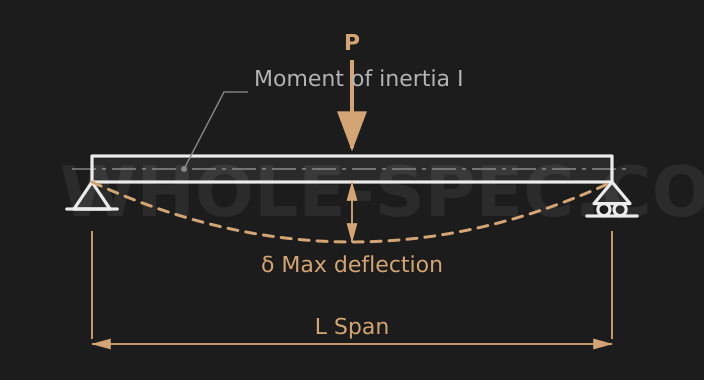
Support Type
Load Type
Beam Parameters
Material & Section
What It Calculates
Calculates deflection δ, bending moment M, and bending stress σ for simply supported and cantilever beams under point or distributed loads — a quick stiffness and safety check for a beam in early design.
Key Formulas
Simply supported with a central point load: δ=PL³/48EI, M=PL/4. Uniformly distributed: δ=5wL⁴/384EI, M=wL²/8. Cantilever with an end load: δ=PL³/3EI, M=PL. Bending stress σ=M·y/I, where y is the distance from the neutral axis to the outermost fiber.
Inputs
L is the beam length (mm), P the point load (N), w the distributed load (N/mm), and E the elastic modulus (steel 210, stainless 193, aluminum 70 GPa). Choose a rectangular, round, or pipe section and the second moment of area I and y are computed automatically.
Worked Example
For a 1000 mm simply supported beam with a central point load P=1000 N, steel (E=210 GPa), and a 50×50 mm square section: I=bh³/12=520,833 mm⁴, δ=PL³/48EI≈0.19 mm, M=PL/4=250,000 N·mm, and σ=M·y/I≈12 MPa (y=25 mm).
Beam Deflection Calculator — US Engineering Practice
Beam deflection analysis is a cornerstone of structural and mechanical design in US practice, governed by classical beam theory and codified in resources such as Roark's Formulas for Stress and Strain and the AISC Steel Construction Manual. Whether you are sizing a W8×31 wide-flange girder for a mezzanine floor or a 6061-T6 aluminum extrusion supporting conveyor components, accurately predicting deflection prevents serviceability failures long before yield stress is approached. The AISC 360 Specification for Structural Steel Buildings defines both Allowable Stress Design (ASD) and Load and Resistance Factor Design (LRFD) frameworks, each affecting how service loads are combined before entering the deflection formula. For steel, E = 29,000 ksi (200 GPa); for 6061-T6 aluminum, E = 10,000 ksi (69 GPa). A 100 mm (3.937 in) deep W-shape will behave very differently from a 4-in aluminum channel under identical loading — this calculator handles both.
Formula and Methodology
The general midspan deflection for a simply supported beam under uniformly distributed load is δ = 5wL⁴ / (384EI), where w is load per unit length [lb/in or N/mm], L is span length [in or mm], E is elastic modulus [psi or MPa], and I is the second moment of area [in⁴ or mm⁴]. For a concentrated center load, δ = PL³ / (48EI). For a cantilever with end load, δ = PL³ / (3EI). Roark's Formulas (Table 3 through Table 8) tabulates coefficients for over 40 loading configurations, including partial UDL, triangular loads, and overhangs. Section properties for AISC W-shapes, S-shapes, and HSS tubes are tabulated in Part 1 of the AISC Steel Construction Manual; I values are given in in⁴. For US customary: a W10×49 has I_x = 272 in⁴; for metric reference, 272 in⁴ = 113,200 cm⁴. AISC 360 Chapter L limits live-load deflection to L/360 for floor beams and L/240 for roof members under service loads in ASD. LRFD deflection checks use unfactored (service-level) loads.
US Standards and References
- AISC Steel Construction Manual, 16th Edition — Section property tables for W, S, M, C, MC, L, HSS, and pipe shapes; ASD/LRFD design procedures; deflection limits in Chapter L.
- AISC 360-22 Specification for Structural Steel Buildings — Governing code for serviceability criteria; ASD and LRFD load combination requirements affecting deflection checks.
- Roark's Formulas for Stress and Strain, 8th Edition (Young, Budynas, Sadegh) — Comprehensive closed-form deflection and slope equations for all common boundary conditions and load distributions.
Common Engineering Pitfalls
A frequent error in US shop practice is mixing unit systems mid-calculation. If E is entered in psi (lb/in²) and I is in in⁴, then load w must be in lb/in — not lb/ft. A W8×31 with a UDL of 500 lb/ft must be converted to 41.67 lb/in before substituting into the δ formula, or the result will be off by a factor of 12⁴ = 20,736. Dimension notation "500 lb/ft" (6.00 kN/m) appearing on architectural drawings frequently causes this conversion to be overlooked when structural engineers interface with mechanical teams using in-lb units.
A second common pitfall involves composite beams or built-up sections. Engineers sometimes use the tabulated I of the parent W-shape without accounting for cover plates or reinforcing channels, leading to an unconservative (larger) I value and underpredicted deflection. Any welded or bolted addition to a section requires computing the transformed I using the parallel-axis theorem before entering the formula.
Software and Tools
In US engineering practice, beam deflection is frequently checked using RISA-3D, RAM Structural System, and Bentley STAAD.Pro for building structures. For machine structures and custom frames, Autodesk Inventor's frame analysis module and SolidWorks Simulation are widely used. For quick hand-verification and parametric studies, engineers rely on IStructE beam tables or Roark's companion spreadsheets published by AISC. Mastercam and HSMWorks are used for fabrication planning of complex built-up sections but not for deflection calculations directly.
Imperial Conversion Examples
A 120 in (3,048 mm) simply supported steel W6×15 beam (I_x = 9.72 in⁴) carries a 2,000 lb (8.90 kN) center point load. δ = PL³/(48EI) = 2,000 × 120³ / (48 × 29,000,000 × 9.72) = 2,000 × 1,728,000 / 13,531,680,000 = 0.256 in (6.5 mm). Allowable deflection at L/360 = 120/360 = 0.333 in (8.5 mm) — section passes. Note: 29,000,000 psi = 200,000 MPa = 200 GPa.
Common Calculation Questions
Q1: When should I use ASD vs LRFD for deflection checks?
A1: Deflection is always a serviceability check performed with unfactored (service-level) loads, regardless of whether your strength design used ASD or LRFD. AISC 360 Chapter L is explicit: apply the actual expected service loads — dead load, live load, or their combination as appropriate — without load factors when computing deflections against L/360 or L/240 limits.
Q2: My CAD model shows a different I value than the AISC table — which do I use?
A2: Use the AISC tabulated value for standard rolled shapes; it is the reference value for design. CAD-derived moments of inertia can differ slightly due to fillet radius modeling. If you have a custom built-up section not in the tables, verify your CAD model against a hand parallel-axis calculation before using the CAD figure in a deflection formula.
Q3: How do I account for end fixity in this calculator?
A3: The calculator offers pinned-pinned, fixed-fixed, and fixed-free (cantilever) boundary conditions. A fixed-fixed beam under UDL has δ_max = wL⁴/384EI, identical in form to simply supported but occurring at midspan with different reactions. Real connections are rarely fully fixed; AISC recommends assuming simple supports unless the connection is explicitly designed for moment transfer.
Q4: What is a reasonable deflection limit for an aluminum machine frame?
A4: AISC Chapter L targets are written for building structures. For machine frames in US practice, designers commonly apply L/500 to L/1000 for precision equipment per OEM requirements or ASME B5.54 for CNC machine tools. Always verify the allowable deflection with the machine builder's specification rather than using building code defaults.
Q5: Can I use this calculator for curved or tapered beams?
A5: No. Straight prismatic beams only. For curved beams, use Winkler-Bach theory as presented in Roark's Chapter 9. For tapered beams (common in steel rigid frames), AISC Design Guide 25 provides moment amplification factors, and software such as RISA-3D handles tapered members with variable I directly.