Pitch Calculator
Layout Conditions
Layout Mode
What It Calculates
Works out the pitch (spacing) and the coordinate of every item when N holes, bolts, taps, or parts are laid out at equal intervals along a total length L. Handy for hole patterns on a machining drawing, clamp spacing, or fence-post division.
Layout Modes
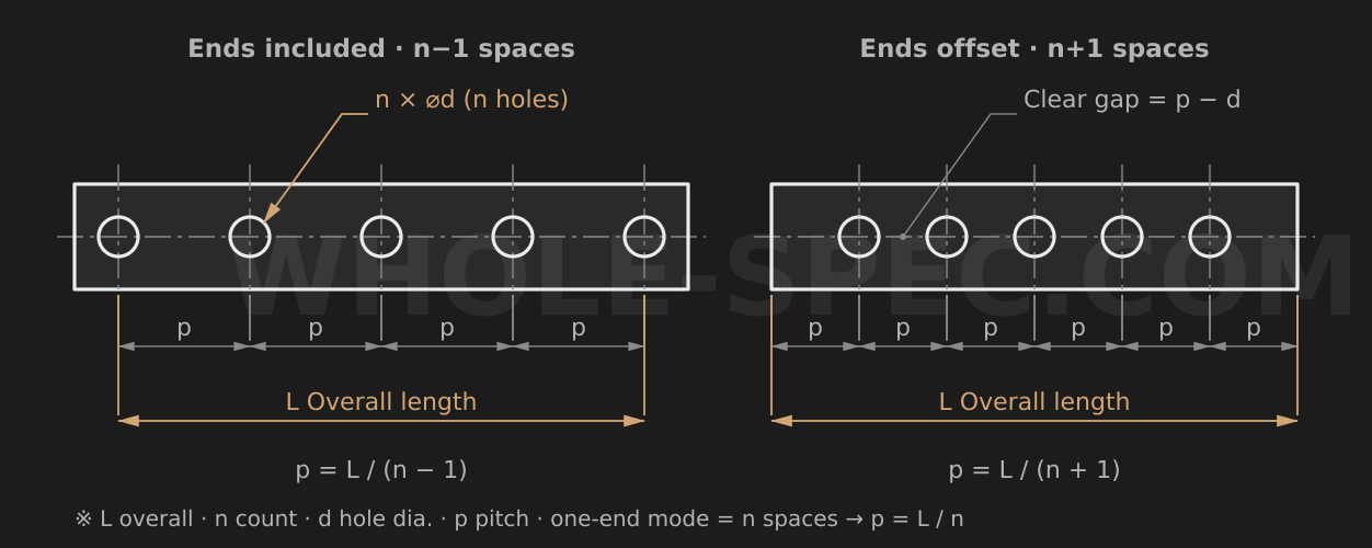
Three modes drive the result. Both Ends Included puts the first and last items on the two endpoints, splitting L into N-1 spans. Both Ends Margin leaves an equal margin at each end, splitting L into N+1 spans. One End Included starts at one end, splitting L into N spans. The same N gives a different pitch per mode, so fix the drawing datum first.
Key Formulas
Both Ends Included: pitch P=L/(N-1), position of item i is i×P (i=0…N-1). Both Ends Margin: P=L/(N+1), position i×P (i=1…N). One End Included: P=L/N, position i×P (i=0…N-1). Entering an object diameter d also reports the net gap=P−d; a negative gap warns that the objects interfere.
Worked Example
With total length L=500 mm and count N=5: Both Ends Included gives P=500/(5-1)=125 mm with positions 0, 125, 250, 375, 500. Both Ends Margin gives P=500/(5+1)≈83.33 mm with positions 83.33, 166.67, 250, 333.33, 416.67. One End Included gives P=500/5=100 mm with positions 0, 100, 200, 300, 400. Adding d=20 mm yields gap=125-20=105 mm in Both Ends mode, so no interference.
Notes
N is clamped to a minimum of 2 and rounded to an integer. Switching the length unit to inch converts both inputs and results to inch. Positions are measured to the center of each object, so for hole machining check edge distance and tolerances separately.
Thread Pitch Calculator — US Engineering Practice
Thread pitch selection determines how a fastener or leadscrew translates rotary motion to linear force, how fine a positional adjustment it permits, and whether it will self-lock under vibration. In the United States, the dominant thread standards are ASME B1.1 (Unified Inch Screw Threads: UNC, UNF, UNEF, and 8-UN series) and ASME B1.13M (Metric Screw Threads: M and MJ profiles). Beyond fasteners, power screws use Acme threads (ASME B1.5) and stub Acme (ASME B1.8) for lead screws, jack screws, and valve stems where efficiency and wear resistance matter. Pipe threads — NPT (National Pipe Taper, ASME B1.20.1) — appear throughout US process piping and pneumatic systems. Understanding pitch, lead, starts, and the lead-pitch relationship for multi-start threads is critical for both fastener torque-tension calculations and machine lead screw performance predictions.
Formula and Methodology
Pitch (p) = 1 / TPI for inch threads [in], where TPI = threads per inch. Lead (L) = p × n_starts. For single-start threads, lead = pitch. Example: ½-13 UNC has TPI = 13, p = 0.0769 in (1.954 mm), lead = 0.0769 in per revolution. A 2-start ½-10 Acme thread has p = 0.100 in (2.54 mm), lead = 0.200 in per revolution. For metric: M10×1.5 has pitch = 1.5 mm (0.0591 in). Helix angle: λ = arctan(L / π × d_m), where d_m is the mean thread diameter. Self-locking condition: λ < φ (friction angle), where tan(φ) = µ (coefficient of friction). For µ = 0.15 (dry steel), φ ≈ 8.5°; most UNC fasteners with λ < 5° are self-locking, confirming why standard bolts do not back out under static load without vibration.
US Standards and References
- ASME B1.1-2003 — Unified Inch Screw Threads — Defines UNC, UNF, UNEF, 4-UN, 6-UN, 8-UN, 12-UN, 16-UN series with tolerance classes 1A/1B through 3A/3B; the governing US standard for fastener threads.
- ASME B1.5-1997 — Acme Screw Threads — Defines general purpose and centralizing Acme profiles for power screws; includes lead and pitch relationships for multi-start threads used in machine tool leadscrews and actuators.
- ASME B1.20.1-2013 — Pipe Threads, General Purpose (Inch) — Governs NPT taper pipe threads (1 in 16 taper), NPTF (Dryseal), and straight pipe thread (NPS) dimensions for US plumbing, hydraulic, and pneumatic fittings.
Common Engineering Pitfalls
The most dangerous thread error in US practice is confusing lead and pitch on multi-start threads. A 4-start ball screw with 5 mm pitch has a lead of 20 mm — it advances 20 mm per revolution, not 5 mm. This error in lead screw selection causes positioning errors by a factor equal to the number of starts: a CNC axis programmed with the wrong lead will be off by 4× on every commanded move, and this error will not be caught by encoders if the encoder reads motor revolutions rather than linear position directly.
A second pitfall is applying UNC thread engagement length rules to high-strength applications without checking thread shear area. The commonly cited rule "thread engagement = 1×D for steel" is derived from an assumption that the screw will fail in tension before the thread strips. For Grade 5 (SAE J429) and Grade 8 fasteners into ductile cast iron or aluminum tapped holes, this rule is insufficient — minimum engagement must be computed from thread shear area formulas per IFI Handbook of Fastener Technology, accounting for the lower shear strength of the tapped material.
Software and Tools
Thread selection and engagement length calculations are handled in US practice by the IFI Fastener Standards Book (online and print editions), which includes thread data, proof loads, and engagement length tables for all UNC/UNF sizes. For threaded connections in pressure vessels, ASME PCC-1 provides bolt-up procedure guidance. Mastercam's thread milling module accepts ASME B1.1 thread data directly for generating thread mill toolpaths. SolidWorks Toolbox and PTC Creo include complete ASME and ISO thread libraries. For lead screw selection, Thomson Industries and Nook Industries publish US-unit lead screw selection guides with efficiency, back-drive, and critical speed calculations.
Imperial Conversion Examples
¾-10 UNC: TPI = 10, p = 0.1000 in (2.540 mm), minor diameter = 0.6273 in (15.93 mm). Metric near-equivalent: M20×2.5 (p = 2.5 mm = 0.0984 in, d = 20 mm = 0.787 in) — not interchangeable. 1-in NPT: TPI = 11.5 (tapered), effective pitch = 0.0870 in (2.21 mm). 1-in NPS (straight): TPI = 11.5, p = 0.0870 in. Note: NPT nominal size refers to historical pipe bore, not actual OD; 1-in NPT OD = 1.315 in (33.4 mm).
Common Calculation Questions
Q1: When should I use UNF instead of UNC for a structural fastener?
A1: UNF (fine pitch) provides approximately 10% greater tensile stress area than UNC at the same nominal diameter, giving marginally higher bolt load capacity. UNF is preferred in thin-walled tapped holes where UNC pitch would leave insufficient thread engagement, and in precision adjusting mechanisms. However, UNF is more susceptible to cross-threading during assembly and more sensitive to contamination. For general structural use, UNC is the US standard choice per IFI and AISC practice.
Q2: What is the difference between Class 2A/2B and Class 3A/3B threads?
A2: ASME B1.1 Class 2A/2B is the standard commercial tolerance class — allowing moderate clearance for ease of assembly and coating accommodation. Class 3A/3B is a tighter tolerance class (zero allowance) used for precision fits, gaging threads, and critical structural connections. Class 3A threads are commonly specified for aerospace fasteners (NAS, MS, AN series) where positional accuracy and load concentration across more thread flanks is important.
Q3: How do I calculate the advance per degree of rotation for a leadscrew?
A3: Advance per degree = Lead / 360. For a 5-start M20×4 mm pitch ball screw (lead = 20 mm): advance per degree = 20/360 = 0.0556 mm/° (0.00219 in/°). For manual adjustment screws, the advance per graduation on the thimble depends on the thimble circumference division; most US micrometers use 0.001-in pitch with 25 divisions, giving 0.001/25 = 0.00004 in (1 µm) per graduation.
Q4: Is NPT thread interchangeable with BSPT (British Standard Pipe Taper)?
A4: No. NPT has a 60° thread form (ASME B1.20.1) and tapers 1 in 16 (3/4 in/ft). BSPT (BS EN 10226) has a 55° Whitworth thread form and tapers 1 in 16 but with different pitch values (TPI per Whitworth series). NPT and BSPT will cross-thread and can create a falsely tight make-up while leaking under pressure. Always specify NPT for US pneumatic and hydraulic systems and use adapters when connecting to BSP-equipped imported components.
Q5: What is the recommended thread engagement length for an aluminum tapped hole receiving a Grade 8 bolt?
A5: For 6061-T6 aluminum (F_su ≈ 30,000 psi shear) receiving an ASTM A574 (Grade 8 equivalent) bolt, minimum engagement = 1.5×D. For larger diameters above ¾ in, verify using IFI thread shear area formulas because bolt proof load scales with D² while thread shear area scales with D×L_e. A helical coil insert (Heli-Coil, Keensert) effectively converts the tapped hole to a steel thread and allows engagement of 1.0×D.