Ad
Parallel Key Spec Table
Parallel Key Specifications — 48 sizes
KS B 1311JIS B 1301DIN 6885
A rectangular-section key inserted between a shaft and hub to transmit torque. The most common shaft-hub fastening method.
Practical Notes
- Key length should be 1.0–1.5× hub length. Too short causes excessive surface pressure and deformation; too long creates stress concentration.
- Always specify R or chamfer on keyway corners. Sharp corners cause stress concentration leading to shaft fatigue failure.
Selection Guide
The most common method for transmitting torque between shaft and hub. Key cross-section (b×h) is determined by shaft diameter per KS/ISO. Key length should be 1.0–1.5× hub length. Choose Type A (round both ends), B (square), or C (one round) based on keyway machining method.
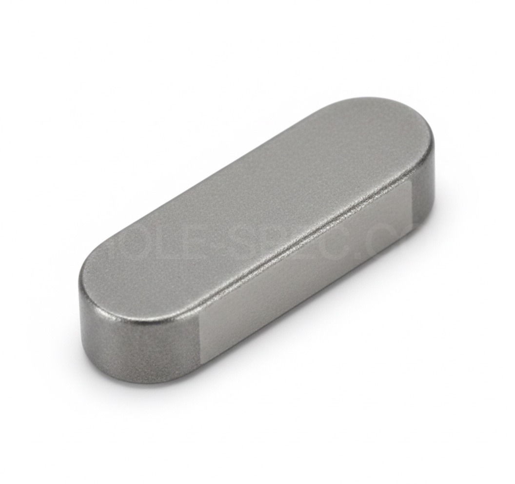 Parallel Key
KSJISDINParallel Key
12 sizesThe dimensions below are identical across KS B 1311 · JIS B 1301 · DIN 6885.
| Nominal | b | h | Shaft Dia | Standard | - |
|---|---|---|---|---|---|
| 2×2 | 2 | 2 | 6~8 | KS B 1311 | - |
| 3×3 | 3 | 3 | 8~10 | KS B 1311 | - |
| 4×4 | 4 | 4 | 10~12 | KS B 1311 | - |
| 5×5 | 5 | 5 | 12~17 | KS B 1311 | - |
| 6×6 | 6 | 6 | 17~22 | KS B 1311 | - |
| 8×7 | 8 | 7 | 22~30 | KS B 1311 | - |
| 10×8 | 10 | 8 | 30~38 | KS B 1311 | - |
| 12×8 | 12 | 8 | 38~44 | KS B 1311 | - |
| 14×9 | 14 | 9 | 44~50 | KS B 1311 | - |
| 16×10 | 16 | 10 | 50~58 | KS B 1311 | - |
| 18×11 | 18 | 11 | 58~65 | KS B 1311 | - |
| 20×12 | 20 | 12 | 65~75 | KS B 1311 | - |
Key Features
- Rectangular cross-section (b×h); KS B 1311 / DIN 6885-1; key size determined by shaft diameter
- Round both ends (Type A) / square both ends (Type B) / one round end (Type C)
- S45C or SUS304 material; transmits torque via side-fit in shaft and hub keyways
Key Applications
Motor-reducer shaft coupling, pulley/sprocket fixing, pump impellers, fan hubs, coupling shafts
FAQ
How is key cross-section (b×h) determined?
Determined by shaft diameter per KS B 1311 / DIN 6885-1. Example: ø25 shaft→key b8×h7, ø40→b12×h8. Refer to spec tables.