Fit Tolerance Calculator
Quick Select (Common Fits)
Basic Size & Tolerance Zones
What It Calculates
Determines how a hole and shaft specified by ISO 286 (KS B 0401) tolerance symbols actually mate. Enter the basic size and the hole and shaft symbols, and it returns each size limit and deviation, classifies the joint as clearance, transition, or interference, and reports the maximum and minimum clearance or interference in micrometres.
Inputs
Only three inputs: the basic size D (mm, 1 to 500), the hole symbol (uppercase, e.g. H7), and the shaft symbol (lowercase, e.g. g6). The letter sets the fundamental-deviation position and the number the IT grade (tolerance width). The Quick Select list fills both symbols for common pairings such as H7/g6.
Key Formulas
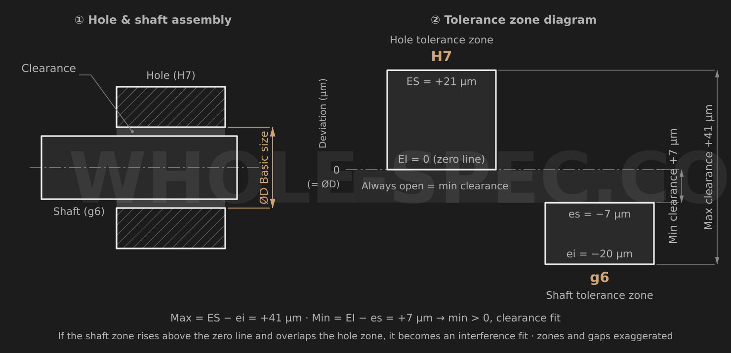
Limits are built from the IT table (by size band) and the fundamental-deviation table. Hole H has lower deviation EI=0 and upper ES=+IT. For shafts a–h the upper deviation es equals the fundamental deviation and ei=es−IT; for k–u the lower deviation ei equals the fundamental deviation and es=ei+IT; js/JS is symmetric at ±IT/2. The fit is judged from max clearance=ES(hole)−ei(shaft) and min clearance=EI(hole)−es(shaft): min clearance above zero is clearance, max clearance below zero is interference, and a span across zero is transition.
Worked Example
Take ø30 H7/g6. At 30 mm (the 18–30 band) IT7=21 µm and IT6=13 µm. Hole H7 has EI=0, ES=+21, giving ø30.000–ø30.021. Shaft g6 has fundamental deviation es=−7 and ei=es−IT=−7−13=−20, giving ø29.980–ø29.993. Max clearance=21−(−20)=41 µm=0.041 mm; min clearance=0−(−7)=7 µm=0.007 mm. Min clearance is positive, so it is a clearance fit, always leaving a 0.007–0.041 mm gap — a precision sliding joint.
Cautions
Results are room-temperature geometric values only. Real assembly is affected by surface roughness (peak flattening reduces effective interference), thermal expansion (shrink-fit heating, operating temperature differences), the pressing method, and material yield — so interference fits need a separate press-force and stress check. Also, the same symbol gives different IT and fundamental deviation in another size band, so enter D accurately.
Fit Tolerance Calculator — US Engineering Practice
Fit and tolerance selection determines whether mating parts will assemble, function, and survive their design life — it is the language through which designers communicate dimensional intent to machinists. In the United States, two parallel systems coexist: the ISO 286 system (H7/g6, H8/f7, H7/p6) widely used in metric designs and increasingly mandated by OEM customers integrating global supply chains, and the ANSI B4.1 system (RC, LC, LT, LN classes) that remains the primary reference in inch-dimensioned drawings for domestic machinery, pumps, and tooling. Mahr and Mitutoyo air gauging systems, the standard for production bore and shaft measurement in US precision machining shops, are configured directly to ISO tolerance grades or ANSI limit values. Understanding both systems — including how to convert between them — is essential for engineers working in today's mixed US manufacturing environment where a 25 mm (0.984 in) H7/g6 bearing fit and a 1-in RC3 fit may appear on adjacent drawings for the same assembly.
Formula and Methodology
ISO 286 defines fundamental deviations by letter (A–ZC for shafts, a–zc for holes) and tolerance grades IT1–IT18. For an H7/g6 fit: H7 hole fundamental deviation = 0 (no lower deviation from nominal); g6 shaft fundamental deviation is negative (shaft smaller than nominal). Tolerance values: IT6 and IT7 are computed as i × multiplier, where i (micron) = 0.45 × D^(1/3) + 0.001D (D in mm, D = geometric mean of diameter step). ANSI B4.1 defines nine running/clearance classes (RC1–RC9), eleven location clearance classes (LC1–LC11), six transition classes (LT1–LT6), and three interference/locating classes (LN1–LN3). For a 1-in shaft: RC3 gives hole +0.0010/−0.000 in, shaft −0.0005/−0.0009 in (min clearance 0.0005 in, max clearance 0.0019 in). ASME B89.1.5 governs the measurement equipment used to verify these fits.
US Standards and References
- ANSI B4.1 — Preferred Limits and Fits for Cylindrical Parts — The inch-series standard defining RC, LC, LT, and LN fit classes; used in domestic US machinery drawings and referenced by ASME Y14.5 for inch tolerancing.
- ISO 286-1 / ASME B4.2 — ISO Limits and Fits — Metric fit system increasingly mandated by automotive and aerospace OEMs; ASME B4.2 is the US adoption of ISO 286 for metric inch hybrid drawings.
- ASME B89.1.5 — Measurement of Plain External Diameters — Calibration and measurement uncertainty requirements for bench micrometers, air gauges (Mahr, Mitutoyo), and CMMs used to verify shaft and bore fits in production.
Common Engineering Pitfalls
A persistently common error is applying ISO H7/g6 tolerance values calculated for a metric nominal diameter to an inch-dimensioned drawing without converting the tolerance band. A 1-in (25.4 mm) H7 bore has a tolerance of +0.0010 in (+25 µm) per ISO 286, while a 25 mm H7 bore has a tolerance of +0.0010 in (+25 µm) — coincidentally similar at this size, but at larger diameters (above 80 mm / 3.150 in), the divergence becomes significant. Engineers must always compute tolerance from the actual nominal dimension, not interpolate from a neighboring table entry.
A second pitfall involves surface finish requirements for interference fits. An H7/p6 press fit requires a bore surface roughness no worse than Ra 1.6 µm (63 µin) to achieve full theoretical interference contact; a rough bore (Ra 3.2 µm / 125 µin) effectively reduces interference by consuming the peaks of the surface profile, potentially converting a designed LN3 interference fit into a loose transition fit in service. US shop drawings must specify Ra on fit surfaces explicitly — ASME Y14.36M governs surface texture symbols on US drawings.
Software and Tools
Sigmetrix CETOL 6σ is the premier US tolerance analysis tool, handling both ISO and ANSI tolerance schemes with Monte Carlo and worst-case analysis. PTC Creo and SolidWorks both include tolerance analysis modules that accept H/h ISO designations. For production gaging, Mahr's MarWin software and Mitutoyo's MeasurLink integrate SPC control charts directly with air gauge readings, alerting operators when bore or shaft trends approach their tolerance limits. ACE SizingMaster, while primarily used for shock absorbers, includes bearing fit guidance tables for housing tolerancing.
Imperial Conversion Examples
1-in nominal RC3 fit (ANSI B4.1): Hole = 1.0000/+0.0010 in (25.400/+0.025 mm). Shaft = 1.0000/−0.0005/−0.0009 in (25.400/−0.013/−0.023 mm). Min clearance = 0.0005 in (0.013 mm). Max clearance = 0.0019 in (0.048 mm). ISO 286 equivalent: approximately 25 mm H7/g6. Note: 0.001 in = 25.4 µm; 0.0001 in = 2.54 µm (a common US shop "tenth").
Common Calculation Questions
Q1: When should I specify H7/g6 versus RC3 on a US drawing?
A1: Use ISO H7/g6 notation on metric-dimensioned drawings per ASME B4.2 whenever the part will be machined or inspected against ISO tolerance software — common in automotive, medical device, and multinational OEM supply chains. Use ANSI B4.1 RC3 notation on inch drawings for domestic US machinery. Mixing systems on the same drawing is poor practice and should be avoided per ASME Y14.5.
Q2: What is the difference between a transition fit and a clearance fit?
A2: A clearance fit (RC or LC class) always has a positive gap between mating parts. A transition fit (LT class) may result in either slight clearance or slight interference depending on where each part falls within its tolerance band. Transition fits are used for locating features (dowel pins, keys) where repeatable positioning matters more than guaranteed assembly without pressing.
Q3: How do I select fit class for a rolling element bearing housing?
A3: Rolling element bearing manufacturers (SKF, Timken, NSK) publish housing and shaft fit tables in their engineering catalogs, specifying ISO tolerance designations by bearing series and loading type. For a light-loaded 6205 ball bearing, a J7 housing bore and k5 shaft are typical. Never use fit tables designed for plain bearings when selecting rolling bearing fits — interference requirements differ significantly.
Q4: What temperature compensation is needed for aluminum-to-steel fits?
A4: Aluminum's thermal expansion coefficient is approximately 13 µin/in/°F (23.4 µm/m/°C), versus steel's 6.3 µin/in/°F (11.3 µm/m/°C). A 1-in aluminum bore assembled with a steel shaft at 70°F (21°C) will lose approximately 0.00067 in (17 µm) of interference for every 100°F (56°C) rise. For elevated-temperature service, compensate by specifying additional interference at room temperature assembly to ensure the fit remains tight at operating temperature.
Q5: What gaging method is best for verifying H7 bores in production?
A5: Air gauging (Mahr Millimess, Mitutoyo AG series) provides non-contact, high-speed measurement at 0.1 µm (0.000004 in) resolution and is the US production standard for H7 and tighter grades on smooth bores. CMM contact probing is used for irregular features and first-article inspection. Plug gauges (GO/NO-GO per ASME B89.1.6) provide pass/fail verification but do not give dimensional data for SPC trending.