Bolt Torque Calculator
Bolt Spec
Fastening Condition
What It Calculates
For a metric bolt (M3 to M30) tightened to a chosen strength class and friction condition, it returns the required tightening torque T, the clamp force F it produces, and the tensile stress σ in the threaded section. It also flags the margin against yield, so you can set a torque-wrench value or review a joint design.
Key Formulas
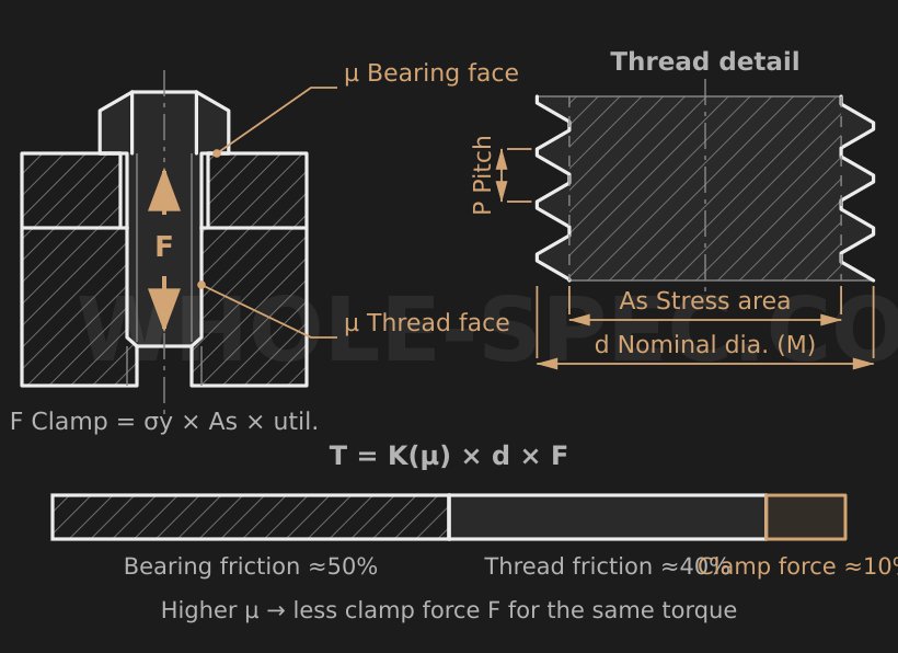
Clamp force is F=σy×As×utilization, and torque is T=K×d×F (d is the nominal diameter in mm, F in N, with T·mm divided by 1000 to give N·m). Tensile stress is σ=F/As. The torque coefficient K scales with friction as K=μ/0.12×0.2, so μ=0.12 gives the standard 0.2 (μ=0.10 gives 0.167, 0.15 gives 0.25, 0.20 gives 0.333). If σ exceeds 90% of the yield strength, a yield-risk warning is shown.
Inputs
Selecting the nominal size M auto-fills the pitch P and stress area As (for example M8 gives P=1.25, As=36.6 mm²). The strength class sets the yield strength σy (4.8=320, 8.8=640, 10.9=940, 12.9=1100, A2-70 stainless=450 MPa). The friction coefficient μ is picked among lubricated/plated 0.10, dry standard 0.12, black oxide 0.15, and stainless no-lube 0.20. Utilization is the fraction of yield used, typically kept at 50 to 75%.
Worked Example
For an M8 bolt, class 8.8 (σy=640 MPa), As=36.6 mm², μ=0.12, and 75% utilization: clamp force F=640×36.6×0.75=17,568 N (about 1,791 kgf), K=0.12/0.12×0.2=0.2, and torque T=0.2×8×17,568/1000≈28.1 N·m (about 287 kgf·cm). Tensile stress σ=17,568/36.6=480 MPa is 75% of the 640 MPa yield and stays below the 90% threshold (576 MPa), so it reads OK.
Notes & Limits
The torque coefficient used here is a simplified empirical relation (K=μ/0.12×0.2) and differs somewhat from detailed methods such as VDI 2230 that separate under-head and thread friction. Real friction varies widely with surface finish, lubrication, and reuse, so treat the output as a first estimate: use a calibrated torque wrench in the field, and back up critical joints with the angle method or direct clamp-force measurement.
Bolt Torque Calculator — US Engineering Practice
Bolted joint integrity is one of the most critical — and most frequently mishandled — elements of US mechanical engineering practice. The torque-tension relationship T = K × D × F provides a simple model for estimating bolt preload from applied torque, but the scatter in actual preload achieved can range from −30% to +50% of the target value even with calibrated torque wrenches, primarily due to variability in the nut factor K. The Industrial Fastener Institute (IFI) Fastener Standards Book is the US industry reference for K-factor values, proof loads, and installation procedures for inch-series fasteners (ASTM A307, A325, A490, A574, F3125) and metric fasteners (ASTM A563, F568M). Nord-Lock washers and thread-locking compounds address the second key concern — vibration loosening — which the torque calculation itself does not prevent. Understanding both the magnitude and the uncertainty of bolt preload is essential for anyone designing critical structural or pressure-containing joints.
Formula and Methodology
Applied torque: T = K × D × F, where T = tightening torque [lb-in or N·m], K = nut factor (dimensionless), D = nominal bolt diameter [in or mm], F = desired bolt preload (clamping force) [lbf or N]. Typical K values: K = 0.20 for as-received zinc-plated steel (dry); K = 0.15 for cadmium-plated (now restricted); K = 0.13 for molybdenum disulfide anti-seize (Loctite LB 8012, Jet-Lube); K = 0.11 for wax/PTFE dry film lubricant; K = 0.20 for hot-dip galvanized (use with caution — varies widely). Design preload F = 0.75 × F_proof (75% of proof load) is the US standard target per IFI and AISC for structural joints. Proof load F_proof = A_t × S_p, where A_t = tensile stress area [in²] per ASME B1.1, and S_p = proof strength [psi] per ASTM F606. Example: ½-13 UNC Grade 8 (ASTM F3125 Grade A490): A_t = 0.1419 in², S_p = 120,000 psi, F_proof = 17,028 lbf, F_design = 12,771 lbf, T = 0.20 × 0.500 × 12,771 = 1,277 lb-in = 106 lb-ft (144 N·m).
US Standards and References
- IFI Industrial Fastener Institute — Fastener Standards Book, 8th Edition — The definitive US reference for fastener dimensions, material grades, proof loads, K-factor values, and installation torque tables for inch and metric fasteners.
- ASTM F606-16 — Test Methods for Fastener Proof Load and Mechanical Properties — Governs proof load testing, hardness testing, and wedge tensile strength verification of bolts, screws, studs, and nuts used in ASTM F3125 Grade A325/A490 structural bolting.
- ASME PCC-1-2019 — Guidelines for Pressure Boundary Bolted Flange Joint Assembly — Governs flange bolt-up procedure for pressure vessels and piping; requires torque pattern, multiple pass tightening, and documentation for Class 300 and above flanges.
Common Engineering Pitfalls
The most dangerous pitfall in US bolt torque practice is applying a dry K-factor torque value to a lubricated bolt — or vice versa. Using K = 0.20 (dry) to calculate installation torque, but then applying anti-seize (K = 0.13) to the actual bolt during assembly, results in preload 54% higher than intended: T/(K_actual × D) vs T/(K_design × D) = 0.20/0.13 = 1.54. On ASME Section VIII pressure vessel flanges or AISC slip-critical connections, this overtorque can yield the bolt body or cause galling of stainless threads. All torque tables must clearly state the lubrication condition assumed, and field personnel must be trained to match the table condition to actual assembly practice.
A second pitfall involves torque wrench accuracy and calibration. A ±4% accuracy class torque wrench (ISO 6789 Class II Grade B) — the US shop standard — contributes ±4% to torque variation. Combined with K-factor scatter of ±25–30%, the resulting preload range can be +40% to −30% of target. For critical joints (ASME PCC-1 Category III), US practice supplements torque control with direct tension indicators (DTI washers, ASTM F959) or turn-of-nut method per AISC RCSC Specification Section 8.2 to verify preload independently of torque measurement.
Software and Tools
Bossard's SmartBolting app and SPS Technologies' Joint Designer are widely used in US aerospace and automotive for bolted joint analysis, implementing VDI 2230 methodology with ASTM material properties. AISC Design Examples (freely downloadable) include worked bolt group analyses for slip-critical connections. ACE SizingMaster does not cover bolt torque, but its stiffness analysis functions complement joint compression analysis. For flange joint analysis per ASME PCC-1, software packages include Dynaflow Research's FLANGE and Intergraph COADE Caesar II with flange stress module. Nord-Lock's Bolt Toolbox provides preload calculations accounting for embedding relaxation.
Imperial Conversion Examples
M16-2.0 Class 10.9 metric bolt: D = 16 mm (0.630 in), A_t = 157 mm² (0.243 in²), S_p = 830 MPa (120,400 psi), F_proof = 130,300 N (29,290 lbf), F_design = 0.75 × 130,300 = 97,725 N (21,968 lbf). Using K = 0.20 dry: T = 0.20 × 0.016 m × 97,725 N = 313 N·m (231 lb-ft). Using anti-seize K = 0.13: T = 203 N·m (150 lb-ft). Note: 1 N·m = 0.7376 lb-ft; 1 lbf = 4.448 N.
Common Calculation Questions
Q1: Why is the recommended design preload 75% of proof load rather than 100%?
A1: The 25% margin between design preload and proof load accounts for torque wrench inaccuracy, K-factor scatter, and dynamic service loads that can add to bolt tension. Proof load (typically 85–92% of minimum yield) is the maximum load that should be applied without permanent set — tightening to 75% of proof load ensures the bolt remains in the elastic range even with ±25% scatter in actual preload, preventing yielding that would require bolt replacement.
Q2: When should I use the turn-of-nut method instead of torque control?
A2: The turn-of-nut method (AISC RCSC Specification) provides more reliable preload than torque control in structural steel bolting because it is displacement-based rather than force-based, eliminating K-factor uncertainty. It is mandatory for AISC slip-critical (Class A and B) connections with A325 and A490 bolts. For precision machinery joints where bolt elongation measurement (ultrasonic bolt gaging) is practical, direct elongation measurement is even more reliable than either method.
Q3: Does Loctite threadlocker affect the K-factor and required torque?
A3: Yes. Loctite 243 (medium strength) and 271 (high strength) act as a controlled lubricant during installation, reducing effective K to approximately 0.12–0.15 and requiring a torque reduction of 20–35% compared to dry installation tables. Henkel (Loctite) publishes application-specific torque tables. Do not use standard dry installation torque with threadlocker — the bolt will be overtorqued at installation and may yield, while the cured Loctite holds the joint against vibration.
Q4: What is the correct torque sequence for a multi-bolt flange per ASME PCC-1?
A4: ASME PCC-1-2019 requires a minimum of three torque passes in a star (cross) pattern for circular flanges: Pass 1 at 30% target torque, Pass 2 at 70%, Pass 3 at 100%. For Class 600 and above, or for heat exchanger flanges, a fourth pass (snug check) is recommended. Pass direction must be cross-bolt, not sequential clockwise, to ensure uniform gasket compression. Documenting the sequence, torque wrench serial number, calibration date, and lubricant used is required for ASME Section VIII documentation packages.
Q5: How much preload is lost to embedding relaxation after initial bolt-up?
A5: Embedding relaxation from surface asperities flattening under compressive load typically causes 5–15% preload loss within the first 24 hours after bolt-up, depending on surface finish, number of interfaces (each gasket/washer/flange face junction contributes), and bolt-to-joint stiffness ratio. ASME PCC-1 and VDI 2230 both account for embedding by specifying a retorque pass 24–48 hours after initial assembly for critical pressure boundary joints. Embedding is higher in joints with soft gaskets, rough machined faces, or stacked shim packs.