Cylinder Calculator
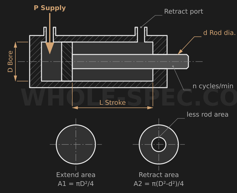
What It Calculates
Computes the extend and retract thrust of a pneumatic or hydraulic cylinder together with the swept air volume per stroke and the per-minute flow demand. Handy in early actuator design for sizing the bore, checking pressure margin, and rating a compressor or valve.
Key Formulas
Extend (head-side) area Ap=π/4·D²; retract (rod-side) annular area Ar=π/4·(D²−d²). Since 1 MPa equals 1 N/mm², thrust falls straight out in newtons: extend Fp=P·Ap, retract Fr=P·Ar. Swept air per stroke V=A·L, and flow demand Q=A·L·n, where n is cycles per minute.
Inputs
D is the cylinder bore (mm), d the piston rod diameter (mm), P the supply pressure (MPa, gauge), L the stroke (mm), and n the cycle rate (per minute). The retract area subtracts the rod cross-section, so it is always smaller than the extend area — and retract thrust and air use shrink accordingly.
Worked Example
With D=50, d=20, P=0.5 MPa, L=100 mm, n=10/min: Ap=π/4·50²=1963.5 mm², Ar=π/4·(50²−20²)=1649.3 mm². Extend thrust Fp=0.5·1963.5≈982 N (about 100 kgf), retract Fr=0.5·1649.3≈825 N (about 84 kgf); swept air per extend stroke V=1963.5·100/10⁶≈0.196 L, and flow demand Q=0.196·10≈117.8 L/min.
Notes
The thrust here is an ideal value ignoring seal friction and back-pressure, so in practice count on only about 50–70% of it as usable force and keep a safety margin against the load. The air and flow figures are free-air values based on swept volume; actual standard-atmosphere consumption is larger by the compression ratio (roughly (P+0.1)/0.1 from gauge pressure). Factor this in when sizing a compressor.
Pneumatic Cylinder Force Calculator — US Engineering Practice
Pneumatic cylinders are the workhorses of US industrial automation, clamping, and actuation systems. Sizing them correctly requires understanding the relationship between shop air supply pressure, cylinder bore, and the real-world efficiency losses introduced by seal friction, back-pressure, and pressure drop in supply lines. In the United States, shop air is conventionally maintained at 80–120 psi (5.5–8.3 bar); most pneumatic circuit designers target 80–100 psi (5.5–6.9 bar) as the design working pressure with a 60 psi (4.1 bar) minimum at the cylinder port to accommodate compressor cycling and distribution losses. NFPA T3.6.7 R3 (Fluid Power — Pneumatic — Cylinder Specification, Inch Series) is the governing US standard for bore, stroke, and port sizes, while ISO 15552 covers the equivalent metric (SI) family. Understanding both is essential when sourcing cylinders from US distributors (Parker Hannifin, Bimba, SMC, Festo) who stock both inch and metric bore sizes.
Formula and Methodology
Theoretical extension force: F_theoretical = P × A, where P is gauge pressure [psi] and A is bore cross-sectional area [in²]. A = π × D² / 4, with D in inches. Practical output force accounts for seal friction: F_actual = P × A × η, where η = 0.85 is the standard efficiency factor for PTFE-seal double-acting cylinders at mid-stroke per NFPA guidelines. For retraction stroke on a double-acting cylinder, net area = π/4 × (D² − d²), where d is rod diameter. Example: 2-in bore, 0.625-in rod, 80 psi → F_extend = 80 × π/4 × 4 × 0.85 = 80 × 3.142 × 0.85 = 213 lbf (948 N). F_retract = 80 × π/4 × (4 − 0.391) × 0.85 = 80 × 2.835 × 0.85 = 193 lbf (859 N). For metric: 50 mm (1.969 in) bore at 6 bar (87 psi) → F = 6 × π/4 × 2500 × 0.85 = 10,011 N (2,250 lbf).
US Standards and References
- NFPA T3.6.7 R3 — Fluid Power: Pneumatic Cylinder Specification (Inch Series) — Defines bore diameters, rod diameters, port sizes, and performance requirements for inch-series cylinders used throughout North American industry.
- ISO 15552 — Pneumatic Fluid Power: Cylinders with Detachable Mountings — Metric cylinder standard applicable when sourcing from European or Asian suppliers; bore sizes 32 mm through 320 mm (1.26–12.6 in).
- Parker Hannifin Pneumatic Division Engineering Reference (Catalog 0900P-E) — Comprehensive US design reference for cylinder selection, speed control, cushioning calculations, and force output tables across the full bore range.
Common Engineering Pitfalls
The single most common sizing mistake in US pneumatic applications is failing to account for back-pressure on the exhaust side. A double-acting cylinder being extended must exhaust the retract side; if the exhaust line includes a flow control valve or long tubing run, exhaust back-pressure can reach 5–15 psi (0.34–1.0 bar), directly subtracting from effective thrust. A cylinder sized at exactly the required force with no back-pressure margin will stall under these conditions. Best practice is to add a 25% force margin above calculated load when sizing, then verify through cycle testing at minimum supply pressure (typically 60 psi / 4.1 bar).
A second pitfall involves bore selection for high-speed applications. Increasing bore to gain force also increases swept volume, raising air consumption proportionally to D². Doubling bore diameter quadruples air consumption per cycle. For high-cycle applications (>60 cycles/min), this drives compressor sizing and energy cost significantly upward. US system designers should calculate SCFM demand per cylinder and verify compressor capacity before committing to a large-bore design.
Software and Tools
Parker Hannifin's PartnerNet and Bimba's online cylinder force calculator are the most widely used US web-based tools for pneumatic sizing. SMC's PneumaticBEAT and Festo's Pneumatic Sizing Tool provide full system sizing including line pressure drop and flow calculations. For integrated PLC and motion systems, Rockwell Automation Studio 5000 Logix Designer includes pneumatic actuator sizing modules. CADENAS PARTsolutions provides CAD models of all major cylinder families in both inch and metric configurations for Mastercam and SolidWorks assembly layouts.
Imperial Conversion Examples
A 1.5-in bore NFPA cylinder at 100 psi: A = π/4 × 1.5² = 1.767 in² (1,139 mm²). F = 100 × 1.767 × 0.85 = 150 lbf (668 N). Same cylinder in metric: bore = 38.1 mm, P = 6.89 bar. F = 6.89 × π/4 × 38.1² × 0.85 / 100 = 6.89 × 1140 × 0.85 / 100 = 668 N. Note: 1 lbf = 4.448 N; 1 psi = 0.06895 bar = 6,895 Pa.
Common Calculation Questions
Q1: Why is 0.85 used as the efficiency factor rather than a higher value?
A1: The 0.85 factor accounts for piston and rod seal friction under normal operating conditions at mid-stroke. At end-of-stroke, where cushions engage, effective output force drops further. For sizing purposes, NFPA and Parker engineering guidance consistently recommend 0.85 as a conservative mid-stroke value; using 0.90 or higher risks undersizing in real installation conditions with aged seals or contaminated air.
Q2: How do I select between NFPA and ISO cylinder mounting when both are available?
A2: Use NFPA inch-series when the host machine is designed to US standards (bolt patterns, port locations in NPT thread). Use ISO 15552 metric when integrating with imported machinery or when the rest of the pneumatic system uses metric fittings and G-thread ports. Mixing series requires adapter plates and adds leak points; standardize to one family per machine wherever possible.
Q3: What is the effect of altitude on cylinder force output?
A3: Gauge pressure is measured relative to atmospheric pressure. At sea level (14.7 psia), 80 psig = 94.7 psia. At Denver (5,280 ft / 1,609 m), atmospheric pressure is approximately 12.2 psia, so 80 psig = 92.2 psia. The gauge pressure and thus the cylinder force calculation is unaffected — only absolute pressure references change. Compressor sizing, however, must account for reduced ambient air density at altitude.
Q4: How do I calculate air consumption for a cylinder cycle?
A4: Volume per cycle (in standard cubic inches, SCI) = (A_bore × L_extend + A_annular × L_retract) × (P_supply + 14.7) / 14.7. Convert SCI to SCFM by multiplying by cycles per minute and dividing by 1,728 (in³/ft³). This figure feeds directly into compressor sizing using the NFPA/Parker system sizing methodology.
Q5: Can I use this calculator for hydraulic cylinders?
A5: The force formula F = P × A × η is identical in form for hydraulic cylinders, but operating pressures are 500–5,000 psi (34–345 bar) rather than 80–120 psi, and efficiency factors are typically 0.90–0.95 for hydraulic seals. The seal friction characteristics differ significantly between pneumatic and hydraulic service; do not apply pneumatic η = 0.85 to hydraulic cylinder sizing.