Bend Calculator
Material & Thickness
What It Calculates
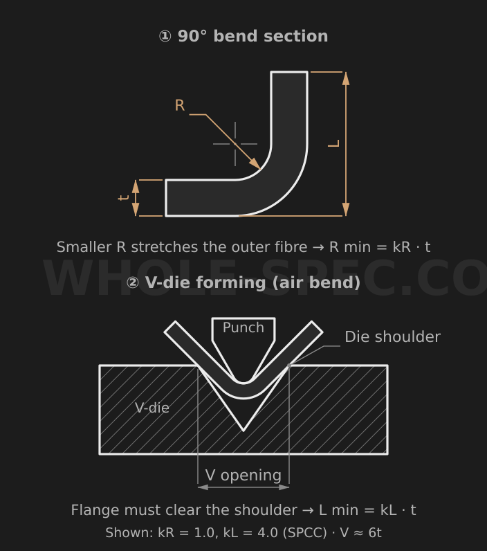
For 90-degree V-bending of sheet metal, this finds the minimum inside bend radius R and the minimum bend height (flange leg length) L that can be formed without cracking, for each material and thickness. Use it to check the safe limit before drafting or designing a bending die.
Key Formulas
Both values scale linearly with sheet thickness t. The minimum bend radius is R(min)=t×kR and the minimum bend height is L(min)=t×kL, where kR and kL are material coefficients. Thicker stock therefore needs proportionally larger R and L. Results assume a 90-degree bend and are given in mm.
Material Coefficients
kR and kL reflect each material ductility and work-hardening. Mild steel (SPCC, SPHC) uses kR=1.0, kL=4.0; hot-rolled SS400 kR=1.5, kL=4.2; stainless SUS304 kR=1.5, kL=4.5; and SUS316, which work-hardens more, kR=2.0, kL=5.0. The ductile A5052 aluminum and C2801 brass use kR=0.5, kL=2.0, while C1100 copper has the lowest values, kR=0.3, kL=1.5.
Worked Example
Bending a t=2.0 mm SUS304 sheet at 90 degrees, with kR=1.5 and kL=4.5, gives R(min)=2.0×1.5=3.0 mm and L(min)=2.0×4.5=9.0 mm. By contrast the more ductile A5052 (kR=0.5, kL=2.0) at t=1.5 mm needs only R(min)=0.75 mm and L(min)=3.0 mm, so it bends with a much tighter radius.
Notes
These are lower limits that prevent cracking, so an actual design should keep R and L at or above them. Bending parallel to the rolling grain raises crack risk, so bend perpendicular to the grain where possible and enlarge R when the bend line runs along the grain. Also, if L is too short the leg slips on the die and the angle goes off, so securing the minimum height matters.
Sheet Metal Bending Calculator — US Engineering Practice
Sheet metal bending is ubiquitous in US manufacturing — from HVAC enclosures and electrical panels to aerospace brackets and automotive stampings. The critical parameter governing bend geometry is the K-factor, which quantifies the shift of the neutral axis during bending. An incorrect K-factor produces parts that are dimensionally out of tolerance after forming, requiring costly rework or scrap. The Precision Metalforming Association (PMA) publishes bend allowance tables and K-factor guidelines specific to material and die radius combinations widely used in North American job shops. For aerospace parts governed by SAE AS-series specifications (AS9100, AS7114), traceability of K-factor values to qualified bend tests is a quality requirement. Press brakes from Trumpf, Bystronic, and Amada — the three dominant brands in US shops — each implement K-factor compensation in their CNC controls, but the default values must be verified against material certs and die setup for critical applications.
Formula and Methodology
Bend allowance (BA) = α × (π/180) × (R + K × T), where α is the included bend angle [degrees], R is the inside bend radius [in or mm], K is the neutral axis factor [dimensionless, typically 0.30–0.50], and T is the material thickness [in or mm]. Bend deduction (BD) = 2 × OSSB − BA, where OSSB (outside setback) = tan(α/2) × (R + T). Flat blank length = L₁ + L₂ + BA (for two-flange parts). For K-factor: soft copper and aluminum bent over R/T < 1 → K ≈ 0.30; cold-rolled steel (CRS) over R/T = 1 → K ≈ 0.33; stainless 304 over R/T = 1 → K ≈ 0.38; hard aluminum 7075-T6 → K ≈ 0.40. PMA recommends minimum inside bend radius of 0.5T for 5052-H32 aluminum and 1.0T for 2024-T3 to prevent cracking at the outer fiber.
US Standards and References
- PMA Precision Metalforming Association — Bend Allowance & K-Factor Tables — Industry-standard reference for K-factor selection, minimum bend radii, and springback allowances for common sheet metals in US production.
- SAE AS7114 / AS9100D — Aerospace quality system and material traceability requirements governing bend test validation for flight-critical formed parts.
- ASME Y14.5-2018 Dimensioning and Tolerancing — Governs how bend dimensions, angular tolerances, and flat pattern dimensions are annotated on engineering drawings in US practice.
Common Engineering Pitfalls
The most common bending error in US shops involves using the default K-factor from the press brake controller without verifying against the actual material lot. Trumpf TruBend controls default to K = 0.33 for steel; however, dual-phase high-strength steel (DP980) used in automotive structural components may require K = 0.38–0.42, shifting the blank layout by several hundredths of an inch on a 12-in (304.8 mm) flat. Over an entire production run of 5,000 parts, this error accumulates as consistent out-of-tolerance flanges.
A second pitfall is neglecting grain direction for aluminum and stainless steel. Bending perpendicular to the rolling direction (across the grain) typically allows smaller minimum radii than bending parallel to rolling direction. For 6061-T6 aluminum plate, minimum inside radius bending perpendicular to grain is 3T, but bending parallel to grain may require 6T to avoid cracking — a difference that can make certain bend orientations physically impossible on thicker plate without annealing first.
Software and Tools
Trumpf's TruTops Bend, Bystronic's BySoft 7, and Amada's Dr. ABE_Blank are the dominant US press brake programming environments, all implementing parametric K-factor and bend sequence optimization. SolidWorks Sheet Metal module and Autodesk Inventor Sheet Metal use K-factor inputs directly in flat pattern computation. For tolerance stackup on bent assemblies, Sigmetrix CETOL 6σ is used in tier-1 automotive and aerospace supply chains to model the cumulative effect of K-factor variation across multiple bends. Manual calculation verification is often performed using PMA's printed bend allowance slide rules or TRUMPF's online bend calculator.
Imperial Conversion Examples
Bending 0.090 in (2.29 mm) thick 5052-H32 aluminum at 90° with R = 0.062 in (1.57 mm): K = 0.33. BA = 90 × (π/180) × (0.062 + 0.33 × 0.090) = 1.5708 × (0.062 + 0.0297) = 1.5708 × 0.0917 = 0.144 in (3.66 mm). If L₁ = 2.000 in and L₂ = 3.000 in, flat blank = 2.000 + 3.000 + 0.144 = 5.144 in (130.7 mm). R/T = 0.062/0.090 = 0.69 < 1.0 — verify against PMA minimum radius table for this alloy before proceeding.
Common Calculation Questions
Q1: What K-factor should I use for 304 stainless steel?
A1: For 304 stainless with R/T between 1 and 3, K = 0.38 is a common US shop default per PMA tables. For tighter radii (R/T < 1), expect K to drop toward 0.33 as the neutral axis moves inward under greater compressive strain. Always confirm against a test bend on the actual material lot for tolerance-critical parts.
Q2: How does springback affect my bend angle?
A2: Springback causes the formed part to open slightly after tooling release. For CRS at 90°, springback is typically 1°–3°; for 7075-T6 aluminum it can reach 5°–8°. US shops compensate by overbending — if the target is 90°, the press brake is programmed to 87°–89°. Modern Trumpf and Amada adaptive bending systems measure springback in real time using angle sensors and adjust ram depth automatically.
Q3: Can I use the same flat pattern for both laser cutting and punching?
A3: Yes — the flat pattern dimension is material- and bend-geometry-dependent, not cutting-process-dependent. However, punching (as opposed to laser cutting) introduces small burr and roll-over at hole edges that can affect tight-tolerance bend locations near perforations. Review PMA guidelines on minimum edge distance from holes to bend lines to prevent tearing.
Q4: Why does my SolidWorks flat pattern differ from my press brake program?
A4: Likely a K-factor mismatch. SolidWorks may use K = 0.33 by default while your Amada control uses K = 0.40 for the same material. Open the SolidWorks sheet metal feature, match the K-factor exactly to your machine's material table, then compare. Differences under 0.005 in (0.13 mm) per bend are common and usually within drawing tolerance.
Q5: What is the minimum flange length for air bending?
A5: Minimum flange length in air bending must exceed the V-die width to prevent the flange from falling into the die opening. Typical US rule: minimum flange ≥ 3×T + R + 1/32 in. For 0.125 in (3.18 mm) steel on a 1-in V-die, minimum flange is approximately 0.5 in (12.7 mm). Bottom bending and coining allow shorter flanges but require much higher tonnage.