Spring Finder
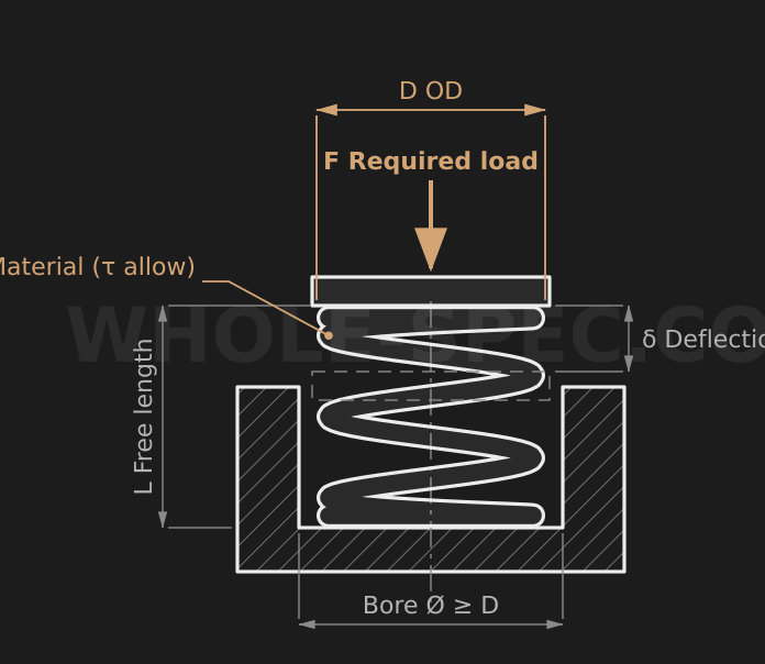
What It Calculates
Knowing only the installation outer diameter D and the load it must carry, it scans standard wire diameters and recommends a workable compression coil spring spec (wire dia, mean dia, index, free length, spring rate). Use it to gauge which wire gauge is realistic before detailed design.
How It Selects
It takes 14 standard wire diameters (0.5–6mm) as candidates and, for each, derives the mean diameter Dm=D−d and the spring index c=Dm/d. Candidates whose index falls outside 4–12, or whose corrected shear stress exceeds the material allowable, are discarded. The survivors are ranked by how close their stress utilization is to 75%, and the top three are shown. Very low utilization (below 15%) is treated as over-design and dropped.
Key Formulas
The load is converted as F=Fkgf×9.81 N. Mean diameter Dm=D−d, spring index c=Dm/d, and the Wahl correction factor K=(4c−1)/(4c−4)+0.615/c. The corrected shear stress is τ=K·8·F·Dm/(π·d³), and utilization is τ/allowable×100%. The spring rate is k=G·d⁴/(8·Dm³·n) with G=78500 MPa and an assumed active coil count n=8, and the deflection is δ=F/k.
Inputs
D is the coil outer diameter (mm) and the required load is entered in kgf. The material sets the allowable shear stress: music wire SWPB 800, hard-drawn SWC 700, and stainless SUS304-WPB 600 MPa. The shear modulus G and active coils n are fixed internally at 78500 MPa and 8, so the suggested free length and coil count are starting-point guidelines only.
Worked Example
For D=20 mm, a 5 kgf load, and stainless (allowable 600 MPa), F=5×9.81=49.05 N. The top pick is wire d=2.0 mm: Dm=18 mm, c=9.0, K≈1.162, τ=1.162×8×49.05×18/(π×2³)≈327 MPa (utilization about 54%). The spring rate k=78500×2⁴/(8×18³×8)≈3.37 N/mm, deflection δ=49.05/3.37≈14.6 mm, and suggested free length L≈64 mm.