Ad
Helical Gear Spec Table
Helical Gear Specifications — 16 sizes
KS B 1401ISO 1328JIS B 1702DIN 3960
A gear with helical teeth offering lower noise and higher efficiency than spur gears. Widely used in reducers and transmissions.
Practical Notes
- Axial thrust is generated — thrust bearings or angular contact bearings are required.
- Larger helix angle reduces noise but increases axial force. Typically 15–25° is optimal.
Selection Guide
Angled teeth reduce noise and increase torque capacity. Better than spur gears for high-speed, heavy-load applications. However, axial thrust is generated, requiring thrust bearings.
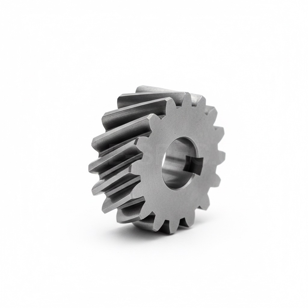 Helical Gear
KSISOJISDINHelical Gear
4 sizesThe dimensions below are identical across KS B 1401 · ISO 1328 · JIS B 1702 · DIN 3960.
| Nominal | m | α | ha | Formula | Use |
|---|---|---|---|---|---|
| M1 Helical | 1 | 20° | 1 | d=mZ/cosβ | Low Noise Reducer |
| M1.5 Helical | 1.5 | 20° | 1.5 | d=mZ/cosβ | Auto Transmission |
| M2 Helical | 2 | 20° | 2 | d=mZ/cosβ | Industrial Reducer |
| M3 Helical | 3 | 20° | 3 | d=mZ/cosβ | Large Transmission |
Key Features
- Helical tooth form twisted at helix angle (β = 15°–30°) relative to axis
- Increased overlap ratio reduces noise and vibration compared to spur gears
- Generates axial thrust load; herringbone pairing or thrust bearing compensation required
Key Applications
Automotive transmissions, machine tool spindle reduction, high-speed industrial reducers, elevator drives, marine gearboxes
FAQ
How to handle helical gear thrust force?
Support with thrust or angular contact bearings. Alternatively, herringbone gears (double helix) cancel thrust forces.