Shock Absorber Calculator
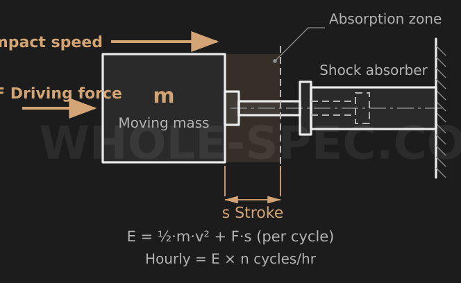
What It Calculates
Combines the kinetic energy of the moving mass at impact with the work done by any additional external force to obtain the energy absorbed per cycle, then multiplies by the cycle rate for the hourly absorbed energy. The mean decelerating force is also reported, so you can match the result against a catalog energy rating (per cycle and per hour) when selecting a model.
Inputs
m is the mass of the moving body (kg), v the velocity just before impact (m/s), F any extra force acting throughout the stroke (N, e.g. cylinder thrust or the gravity component on an incline), s the absorber stroke (mm), and the cycle field the number of impacts per hour. Leave F=0 when no external force is present.
Key Formulas
Kinetic energy Ek=½mv²; external-force energy Ef=F·(s/1000), converting s from mm to m. Energy per cycle E1=Ek+Ef; hourly energy Ehr=E1×cycles. The mean decelerating force is Fmean=2·E1·1000/s (s in mm) — a conservative figure roughly twice the simple average force, approximating the peak reaction under constant deceleration. Divide N by 9.81 for kgf.
Worked Example
For m=20 kg, v=0.8 m/s, F=50 N, s=50 mm, and 500 cycles/hr: Ek=½·20·0.8²=6.4 J, Ef=50·(50/1000)=2.5 J, E1=6.4+2.5=8.9 J, Ehr=8.9·500=4450 J/hr, Fmean=2·8.9·1000/50=356 N (about 36 kgf). Select a model rated above 8.9 J per cycle and 4450 J/hr. As a no-force reference, m=10 kg, v=0.5 m/s, s=25 mm, 300 cycles/hr gives E1=1.25 J, Ehr=375 J/hr, Fmean=100 N.
Notes
Here v must be the actual velocity just before impact — for a body accelerated uniformly over a distance L this is the final, not the average, velocity. In practice apply a safety factor (typically 1.2 to 1.5) to the computed values, and convert rotating or multi-link motion to an equivalent mass. Be sure to satisfy both the catalog maximum energy per cycle and the hourly energy rating; meeting only one risks overheating and shortened life.
Shock Absorber Sizing Calculator — US Engineering Practice
Shock absorber sizing in US industrial automation requires quantifying all energy inputs — kinetic energy from moving mass plus propulsion energy from the drive system — and matching them to a shock absorber's rated energy capacity per cycle and per hour. ACE Controls (headquartered in Farmington Hills, MI) dominates the US industrial shock absorber market; their SizingMaster software is the de facto tool for size selection in US manufacturing and material handling. Enidine Incorporated (ITT subsidiary, based in Orchard Park, NY) serves heavy-duty crane, hoist, and structural applications under ANSI/CMAA 70 and ANSI/CMAA 74 overhead crane standards. Parker Hannifin's Twin Line hydraulic shock absorbers cover heavy automation stops. The sizing calculation must distinguish between self-compensating (fixed orifice) and adjustable models, as adjustable units allow field-tuning deceleration force after installation — critical for multi-weight payloads common in flexible manufacturing cells.
Formula and Methodology
Total kinetic energy: E_k = ½ × m × v² [lb-ft or J], where m is effective mass [slugs or kg] and v is impact velocity [ft/s or m/s]. For US units: m [slugs] = weight [lb] / 32.174. Propulsion energy (cylinder-actuated): E_p = F_cylinder × S_stroke [lb-ft], where F_cylinder is thrust force and S_stroke is stroke of the shock absorber [ft]. Total energy per cycle: E_total = E_k + E_p. Average deceleration force: F_avg = E_total / S_shock, where S_shock is shock absorber stroke [ft]. Maximum deceleration force (assuming constant deceleration): F_max = 2 × F_avg. ACE SizingMaster compares E_total against the rated energy per cycle and rated energy per hour (thermal limit); both must be satisfied. ANSI/CMAA 70 Section 4.6 requires a minimum 3× safety factor on rated capacity for overhead crane buffer applications.
US Standards and References
- ANSI/CMAA 70 — Specifications for Top Running Single Girder Electric Traveling Cranes — Governs end-stop buffer energy absorption requirements for overhead cranes; Section 4.6 defines buffer sizing criteria with minimum 3× energy safety factor.
- ANSI/CMAA 74 — Specifications for Top Running and Under Running Single Girder Electric Traveling Cranes (Under 15 Ton) — Buffer and end-stop specifications for smaller overhead crane applications common in US job shops and warehouses.
- ACE Controls SizingMaster Engineering Guide (ACE-NA-001) — Industry-standard US reference for self-compensating and adjustable shock absorber selection; includes worked examples for conveyor stops, rotary index tables, and cylinder-actuated slides.
Common Engineering Pitfalls
The most common sizing error is forgetting propulsion energy — treating a cylinder-actuated slide as a purely kinetic impact problem and sizing only for ½mv². A pneumatic cylinder at 80 psi driving a 50 lb (22.7 kg) payload through a 2-in (50.8 mm) shock absorber stroke contributes E_p = F_cylinder × S = (80 × π/4 × 2² × 0.85) × (2/12) = 213 × 0.167 = 35.6 lb-ft (48.3 J) of additional energy beyond the kinetic term. On a short-stroke shock absorber with tight energy ratings, omitting this term causes thermal overload failure of the shock absorber within weeks of commissioning, typically manifesting as oil bypass and inconsistent deceleration.
A second pitfall is ignoring the hourly energy rating. A shock absorber may have a per-cycle energy rating of 50 lb-ft (68 J) and a per-hour rating of 2,000 lb-ft/hr (2,712 J/hr). At 40 cycles/min (2,400 cycles/hr) with 1.5 lb-ft (2 J) per cycle, the per-cycle limit is satisfied, but the hourly rate = 2,400 × 1.5 = 3,600 lb-ft/hr (4,882 J/hr) — far exceeding the thermal limit. The shock absorber will reach thermal equilibrium only if average energy dissipation rate stays within its heat rejection capacity. Always check both limits.
Software and Tools
ACE Controls SizingMaster (free, web-based and downloadable) is the primary US tool for industrial automation shock absorber selection; it handles linear, rotary, and overhead applications and outputs a specific ACE model number with adjustment setting. Enidine's online sizing tool covers crane and structural buffer applications per ANSI/CMAA. For integration into machine simulation, Rockwell Automation Arena and Siemens Plant Simulation can model shock absorber energy cycles to validate sizing against hourly throughput. Parker Hannifin's Design Engineering Handbook (Catalog HY14-1900/UK) provides Twin Line shock absorber sizing charts in both US and metric units.
Imperial Conversion Examples
A 200 lb (90.7 kg) pallet moving at 3 ft/s (0.914 m/s) impacts a shock absorber with 1.5-in (38.1 mm) stroke. m = 200/32.174 = 6.215 slugs. E_k = ½ × 6.215 × 9 = 27.97 lb-ft (37.9 J). No propulsion force (gravity roller conveyor). Required F_avg = 27.97/(1.5/12) = 27.97/0.125 = 224 lbf (996 N). Note: 1 lb-ft = 1.356 J; 1 lbf = 4.448 N; 1 ft/s = 0.3048 m/s.
Common Calculation Questions
Q1: How do I account for friction in the conveyor slide when sizing the shock absorber?
A1: Friction forces that resist motion reduce effective impact velocity and thus kinetic energy at impact. Subtract friction work (F_friction × distance to impact) from kinetic energy before sizing. However, friction on the deceleration side (between impact and full stop) reduces required shock absorber energy — this is a conservative simplification to ignore friction on the approach side but include it on the deceleration side.
Q2: What is the self-compensating feature in ACE shock absorbers and when do I need adjustable instead?
A2: Self-compensating (SC series) shock absorbers use a profiled metering pin to deliver constant deceleration force across a range of impact energies — ideal for consistent mass and velocity applications. Adjustable shock absorbers (MA series) allow the operator to tune deceleration force via an external needle valve. Use adjustable models when payload weight varies significantly (>2:1 range) or when the optimal deceleration force must be tuned after installation to minimize bounce-back or vibration in the stopped position.
Q3: Can I use multiple shock absorbers in parallel to increase energy capacity?
A3: Yes, if the mounting geometry ensures simultaneous equal contact with the impacting mass. ACE SizingMaster supports parallel configuration sizing — total energy and force are divided equally among units. Ensure alignment is within 0.010 in (0.25 mm) per foot of spacing to prevent unequal loading that would overload one unit while underloading the other.
Q4: How does the ANSI/CMAA 70 buffer requirement differ from standard automation sizing?
A4: ANSI/CMAA 70 Section 4.6 requires the buffer to absorb the kinetic energy of the crane bridge or trolley at rated load and a minimum speed of 50% of full rated speed, with a minimum 3:1 safety factor on catalog rating. This is significantly more conservative than typical industrial automation sizing, which uses 1.5:1 to 2:1 factors. Always apply the CMAA 3× factor on crane and hoist applications regardless of calculated energy, as the consequences of buffer failure under a suspended load are severe.
Q5: What is the typical shock absorber stroke selection rule for US automation?
A5: ACE's general guideline is to select a stroke length such that the average deceleration force F_avg = E_total / S_shock falls between 50% and 80% of the shock absorber's maximum rated force. This provides margin for variation while ensuring the absorber is working within its design range. Strokes shorter than necessary result in high peak deceleration forces and potential machine frame stress; strokes longer than necessary result in the absorber being underworked and occupying excessive machine envelope.