Spring Calculator
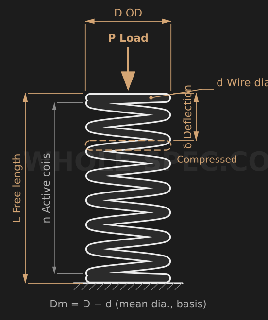
What It Calculates
Computes the spring rate k, the load F at a given deflection, the torsional shear stress τ, and the spring index c for a cylindrical helical compression spring. Knowing only the wire and outer diameters and the active coil count lets you size stiffness and check stress early in design.
Inputs
Enter the wire diameter d (mm), outer diameter D (mm), active coil count n, and deflection δ (mm). The mean coil diameter Dm=D−d is derived internally, so D must exceed d. The free length L field is present but is not used in the k, F, or τ formulas — it is for geometry reference only. The shear modulus is fixed at G=78500 N/mm² for steel.
Key Formulas
Mean diameter Dm=D−d and spring index c=Dm/d. The spring rate is k=G·d⁴ / (8·Dm³·n) and the load F=k·δ. The shear stress applies the Wahl correction factor K=(4c−1)/(4c−4)+0.615/c, giving τ=K·8·F·Dm / (π·d³). K accounts for the stress concentration on the inner coil fiber.
Worked Example
With the defaults d=2 mm, D=18 mm, n=8, δ=10 mm: Dm=16 mm and c=8. k=78500·2⁴ / (8·16³·8)≈4.79 N/mm, F=k·δ≈47.9 N (about 4.88 kgf). The Wahl factor K=(31/28)+0.615/8≈1.184, so τ=1.184·8·47.9·16 / (π·2³)≈289 MPa.
Notes
The formulas assume a steel or stainless wire with G=78500 N/mm². Brass, phosphor bronze, and other materials have a different G, changing both k and τ. A spring index c of 4–12 is generally easy to coil and stable; compare the computed τ against the material allowable shear (e.g. music wire ~800 MPa, SUS304 ~600 MPa) to read the utilization. Check deflection beyond the free length and the solid length separately.
Spring Design Calculator — US Engineering Practice
Compression spring design in US practice is guided by the Spring Manufacturers Institute (SMI) Handbook of Spring Design — the definitive US engineering reference for helical, extension, torsion, disc, and wave springs. Wire material selection follows ASTM standards: ASTM A228 music wire for highest tensile strength in fine wire diameters, ASTM A229 oil-tempered wire for general industrial springs, ASTM A401 chrome-silicon for elevated-temperature and high-cycle applications, and ASTM A313 Type 302 stainless steel for corrosion-resistant springs. Aerospace spring applications require AMS 2430 shot peening to introduce compressive residual stress at the wire surface, substantially improving fatigue life. The Wahl correction factor accounts for stress concentration at the inner wire surface due to curvature — a critical consideration for springs operating near their elastic limit. This calculator implements the standard SMI methodology for compression spring stress, spring rate, and natural frequency.
Formula and Methodology
Spring index C = D/d, where D = mean coil diameter [in or mm], d = wire diameter [in or mm]. Wahl correction factor K_w = (4C−1)/(4C−4) + 0.615/C. Corrected torsional shear stress: τ = K_w × 8 × F × D / (π × d³), where F = applied force [lbf or N]. Spring rate: k = G × d⁴ / (8 × D³ × N_a), where G = torsional modulus of rigidity [psi or MPa] — for music wire G = 11.5×10⁶ psi (79.3 GPa); for 302 stainless G = 10.0×10⁶ psi (68.9 GPa); for 6150 chrome-vanadium G = 11.2×10⁶ psi (77.2 GPa). N_a = number of active coils. Natural frequency (resonance): f_n = (d / (π × D² × N_a)) × sqrt(G / (2 × ρ)), where ρ = wire material density [lb/in³ or kg/m³]. For music wire: ρ = 0.284 lb/in³ (7,860 kg/m³).
US Standards and References
- SMI Handbook of Spring Design (Spring Manufacturers Institute) — The primary US engineering reference for all spring types; includes material property tables, fatigue curves (Goodman diagram), stress correction factors, and end-condition treatment for compression, extension, and torsion springs.
- ASTM A228-16 — Music Wire Specification — Minimum tensile strength requirements for cold-drawn high-carbon steel spring wire; used for the highest-strength applications in fine wire diameters (0.004–0.250 in / 0.10–6.35 mm).
- AMS 2430 — Shot Peening, Automatic — Aerospace Material Specification governing shot peening of spring wire to Almen intensity A or N scale; required for fatigue-critical aerospace and automotive valve springs to prevent surface crack initiation.
Common Engineering Pitfalls
A frequently overlooked pitfall in US spring design is spring surge (resonance) in high-speed applications. If the operating frequency of the machine approaches the spring's natural frequency f_n, coil-to-coil impact occurs, generating stress amplitudes far beyond those predicted by quasi-static analysis. The SMI rule of thumb requires that f_n > 13 × operating frequency for reliable fatigue life. For valve springs in engines and high-speed automation, variable-pitch or conical springs are used to detune the resonant frequency across the operating speed range.
A second common error is ignoring the effect of set (permanent deformation) on as-manufactured springs. Springs with high stress ratios (τ/τ_ult > 0.45) will take a set during initial compression, reducing free length and altering the design load at working height. SMI recommends either designing below the set threshold or specifying that springs be preset (compressed to solid height three times) before shipment, with dimensions measured after presetting. Failure to specify presetting leads to springs that meet initial inspection but deliver low than specified preload in service.
Software and Tools
MSC Software's Spring Design program and Universal Technical Systems (UTS) Spring Design software are widely used in US spring manufacturing. SMI members use proprietary in-house tools implementing the SMI handbook methodology. For finite element fatigue verification of critical springs, ANSYS Mechanical with fatigue module is used in automotive and aerospace programs. Newcomb Spring and Associated Spring (Barnes Group) provide free online spring calculators implementing ASTM material data. For tolerance stack analysis of spring-loaded mechanisms, Sigmetrix CETOL 6σ accepts spring rate uncertainty as a statistical variable in force-deflection chains.
Imperial Conversion Examples
Design example: D = 0.500 in (12.70 mm), d = 0.054 in (1.37 mm), N_a = 10, material = A228 music wire, G = 11.5×10⁶ psi. C = 0.500/0.054 = 9.26. K_w = (4×9.26−1)/(4×9.26−4) + 0.615/9.26 = 36.04/33.04 + 0.0664 = 1.091 + 0.066 = 1.157. k = 11.5×10⁶ × 0.054⁴ / (8 × 0.500³ × 10) = 11.5×10⁶ × 8.50×10⁻⁶ / 10 = 9.78 lb/in (1.71 N/mm). At F = 5 lbf (22.2 N): τ = 1.157 × 8 × 5 × 0.500 / (π × 0.054³) = 23.14 / (π × 1.575×10⁻⁴) = 46,793 psi (323 MPa).
Common Calculation Questions
Q1: What is the maximum allowable torsional stress for a compression spring in static service?
A1: Per SMI Handbook, the maximum allowable corrected stress for A228 music wire in static service is approximately 45% of minimum tensile strength (τ_max = 0.45 × S_ut). At d = 0.054 in, S_ut ≈ 261,000 psi, giving τ_allowable ≈ 117,000 psi (807 MPa). For fatigue service, reduce to 35–40% of S_ut and verify against the Goodman diagram with the actual stress ratio (τ_min/τ_max).
Q2: How do I select between music wire (A228) and oil-tempered wire (A229)?
A2: Music wire (A228) has higher tensile strength at fine diameters (below 0.125 in / 3.18 mm) and is preferred for high-stress, high-cycle springs such as valve springs and miniature mechanisms. Oil-tempered wire (A229) is more economical, available in larger diameters (up to 0.625 in / 15.9 mm), and provides good fatigue life for general industrial springs in moderate-stress applications. Above 0.250 in (6.35 mm) wire diameter, A229 is typically the US default.
Q3: What end condition should I specify for a compression spring to ensure stable seating?
A3: SMI recommends closed and ground ends for most precision spring applications. Closed and ground ends provide flat seating surfaces, reducing angular deflection and lateral instability. Squared (closed) but not ground ends are acceptable for low-force springs where slight angularity is tolerable. Open ends are rarely specified in US practice except for very long, low-rate springs where end cost must be minimized.
Q4: What is the solid height and why is it important?
A4: Solid height L_s = d × N_t (total coils including inactive end coils). The spring must never be compressed to solid height in service, as coil-to-coil contact transfers load through the wire body, generating impact stresses far exceeding design levels. SMI requires a minimum clash allowance of 10–15% of working deflection between the maximum working height and solid height, ensuring the spring never reaches L_s during normal operation.
Q5: How does temperature affect spring performance?
A5: For music wire and oil-tempered wire, the torsional modulus G drops approximately 2% per 100°F (55°C) rise above ambient. A spring rate of 10 lb/in (1.75 N/mm) at 70°F (21°C) will read approximately 9.6 lb/in at 270°F (132°C). For temperatures above 250°F (121°C), specify A401 chrome-silicon wire; above 400°F (204°C), use Inconel 718 or 17-7 PH stainless steel springs, which retain modulus to higher temperatures per AMS 2720 and AMS 5528 specifications.