Gear Calculator
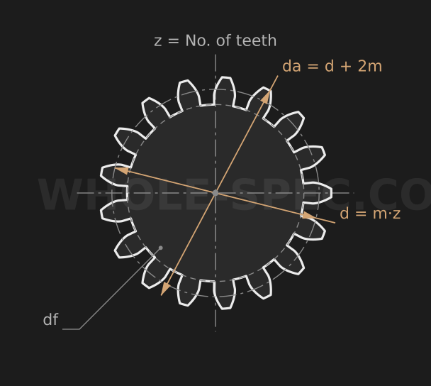
What It Calculates
Derives the basic tooth dimensions of a spur gear from the module m and tooth count z in one step. It returns the pitch diameter d, addendum (tip) diameter da, root diameter df, circular pitch p, and tooth depth h — handy for sizing gear blanks or checking centre distance early on.
Inputs
m is the module, the base size of a tooth (mm); z is the tooth count; α is the pressure angle (°). The industry standard is α=20°, with 14.5° seen on older designs. If you work in inch (DP, teeth/inch), the module converts automatically through m=25.4/DP. The pressure angle α is shown for reference and does not enter the d, da, or df values directly.
Key Formulas
Pitch diameter d=m·z, addendum (tip) diameter da=m·(z+2), root diameter df=m·(z−2.5). Circular pitch p=π·m, and for a standard tooth the depth is h=2.25·m (addendum 1·m plus dedendum 1.25·m). A quick check: da−df equals 2.25·m, the same as the tooth depth h.
Worked Example
With m=2, z=20, α=20°: d=m·z=40 mm, da=m·(z+2)=2·22=44 mm, df=m·(z−2.5)=2·17.5=35 mm. Circular pitch p=π·2≈6.3 mm and tooth depth h=2.25·2=4.5 mm. Note da−df=44−35=9 mm equals 2h (diameters span the depth on both sides), so h itself is 4.5 mm. In inch units DP=25.4/2=12.7 teeth/inch.
Units and Notes
The module formulas (da=m·(z+2), etc.) assume zero profile shift and a standard tooth (addendum factor 1, dedendum factor 1.25). They do not apply directly to profile-shifted gears, helical gears (where normal and transverse modules differ), or non-standard profiles. The centre distance of a meshing pair is a=(d1+d2)/2=m·(z1+z2)/2, and both gears must share the same module to mesh correctly.
Gear Design Calculator — US Engineering Practice
Gear design in the United States is governed primarily by AGMA (American Gear Manufacturers Association) standards, which define rating methodology, geometry, material requirements, and quality grades for spur, helical, bevel, and worm gearing. AGMA 2001-D04 (Fundamental Rating Factors and Calculation Methods for Involute Spur and Helical Gear Teeth) is the authoritative US standard, analogous to ISO 21771 internationally; the two standards use different stress correction factors and safety factor conventions, so they cannot be mixed in a single calculation without explicit conversion. A key source of confusion for US engineers is the difference between the US Diametral Pitch (DP) system and the ISO module (m) system: DP = number of teeth / pitch diameter [in], while m = pitch diameter [mm] / number of teeth. Stocking vendors such as Boston Gear and Martin Sprocket publish catalogs in DP; most imported gears and servo components specify module. The conversion is simply m = 25.4 / DP.
Formula and Methodology
Pitch diameter: d = N / DP (US) or d = m × N (SI), where N = number of teeth. Center distance: C = (N_pinion + N_gear) / (2 × DP) or C = m × (N_pinion + N_gear) / 2. AGMA 2001-D04 bending stress: σ_b = W_t × K_o × K_v × K_s × P_d / (F × Y_j), where W_t = tangential load [lbf], K_o = overload factor, K_v = dynamic factor, K_s = size factor, P_d = diametral pitch [1/in], F = face width [in], Y_j = AGMA geometry factor (from AGMA 908-B89 tables). Contact stress: σ_c = Z_E × sqrt(W_t × K_o × K_v × K_s × K_m / (d_p × F × Z_I)), where Z_E is the elastic coefficient [psi^0.5] and Z_I is the surface geometry factor. For metric per AGMA 2101-D04 (SI adaptation), substitute P_d with 1/m and divide forces in N rather than lbf.
US Standards and References
- AGMA 2001-D04 — Fundamental Rating Factors for Involute Spur and Helical Gear Teeth — Primary US standard for gear strength and durability rating; defines bending (σ_b) and contact (σ_c) stress equations, service factors, and allowable stresses by material grade.
- AGMA 2101-D04 — Fundamental Rating Factors (Metric) — SI-unit version of AGMA 2001, enabling direct calculation in N, mm, and MPa for metric gearing while maintaining AGMA methodology versus ISO 21771.
- AGMA 908-B89 — Geometry Factors for Determining the Pitting Resistance and Bending Strength of Spur, Helical and Herringbone Gear Teeth — Source for Y_j (bending geometry factor) and Z_I (pitting resistance geometry factor) tables used in AGMA 2001 stress equations.
Common Engineering Pitfalls
The most prevalent error in US gear specification is ordering a replacement gear from a vendor by specifying "module 2" when the original gear was DP 16 (which is not equivalent to module 2 — DP 16 = m 1.5875). Gears with different pitch systems will not mesh correctly and will experience immediate flank interference or backlash far outside specification. Always confirm the pitch system on the nameplate or by measuring pitch diameter and tooth count before placing a replacement order.
A second common mistake is applying AGMA service factors without verifying the overload factor K_o against the actual prime mover. AGMA 2001-D04 Table 1 provides K_o values for uniform, moderate shock, and heavy shock prime movers. Engineers sometimes default to K_o = 1.0 for all electric motor drives, but motors with VFD starting can impose 2–3× transient torques that require K_o = 1.25–1.50. Undersized K_o leads to calculated stresses that appear safe but result in early micropitting or bending fatigue in service.
Software and Tools
KISSsoft (widely licensed in US tier-1 automotive and aerospace) and Dontyne Systems Gear Production Suite are the dominant US commercial gear analysis tools, both implementing AGMA 2001 and ISO 6336 in parallel. Dassault Systèmes CATIA Gear Design and SolidWorks Toolbox provide parametric gear generation for layout purposes but lack the rating methodology of dedicated gear analysis software. Boston Gear and W.M. Berg publish free online gear selection tools that compute center distance, velocity ratio, and transmitted power for DP catalog gears. For custom gear cutting, Mastercam supports involute gear generation with form tool or hobbing simulation.
Imperial Conversion Examples
DP 12 spur gear, 24 teeth, 1-in face width, steel AGMA Grade 1: Pitch diameter d = 24/12 = 2.000 in (50.8 mm). Module equivalent m = 25.4/12 = 2.117 mm. Center distance with 36-tooth mating gear: C = (24+36)/(2×12) = 2.500 in (63.5 mm). Pitch line velocity at 1,750 RPM: V = π × d × n / 12 = π × 2.000 × 1750 / 12 = 916 ft/min (4.65 m/s). Transmitted power at W_t = 100 lbf: HP = W_t × V / 33,000 = 100 × 916 / 33,000 = 2.78 HP (2.07 kW).
Common Calculation Questions
Q1: What is the difference between AGMA 2001 and ISO 21771 contact stress results?
A1: AGMA 2001 and ISO 21771 use different stress cycle factors, safety factor conventions, and zone factors (Z_H vs I-factor). For the same gear geometry and loading, ISO 21771 typically yields contact stresses 3–8% higher due to more conservative zone factor treatment. Never mix factors from the two standards in a single calculation. Choose one standard and apply it consistently throughout.
Q2: How do I determine AGMA quality number for a given application?
A2: AGMA quality numbers (now AGMA accuracy grades per AGMA 2000-A88 and AGMA 2015-1-A01) define tooth-to-tooth and total composite error tolerances. For general industrial gear drives, AGMA Q8–Q10 (AGMA 2015 Grade A5–A7) is standard. Precision instrument gearing requires Q12–Q14. Quality number directly affects the dynamic factor K_v — higher quality (lower error) allows higher pitch line velocities before the dynamic factor becomes limiting.
Q3: When should I use a helical gear instead of spur?
A3: Helical gears provide higher load capacity (typically 15–30% over spur at the same face width and DP) due to gradual tooth engagement reducing impact loading and increasing contact ratio. They also operate more quietly. The tradeoff is axial thrust force requiring thrust bearings and more complex housing design. For power gearing above 5 HP (3.7 kW) in continuous service, helical is the US industry default per AGMA recommendations.
Q4: What material AGMA grade should I specify for a general industrial gearbox?
A4: AGMA Grade 1 through Grade 3 define progressively tighter cleanliness and microstructure requirements for through-hardened steel. Grade 1 (AISI 4140, 4340 through-hardened to HB 180–400) is appropriate for most industrial service. Grade 2 and 3 are used for carburized/case-hardened gears in high-cycle applications. Specify the grade in the material note on the gear drawing per AGMA 2001 Appendix A guidance.
Q5: How does backlash relate to gear quality and fit?
A5: Backlash is not specified by AGMA quality number — quality governs tooth profile and lead error, not center distance or tooth thickness. Backlash is controlled by the combination of tooth thickness tolerance and center distance tolerance. AGMA 2002-C16 (Tooth Thickness Specification and Measurement) provides recommended backlash values by normal DP and pitch diameter range. Typical industrial spur gear backlash is 0.001–0.003 in (0.025–0.076 mm) for DP 8–16.